Blender 2.92
Multi In, Multi Out
Blender is an open source 3D Digital Content Creation suite (DCC). Blender currently uses nodes for adjusting parameters of shaders (the texture, and material properties of a 3D object), 2D compositing, and geometry manipulation.
Anatomy of a Blender Node
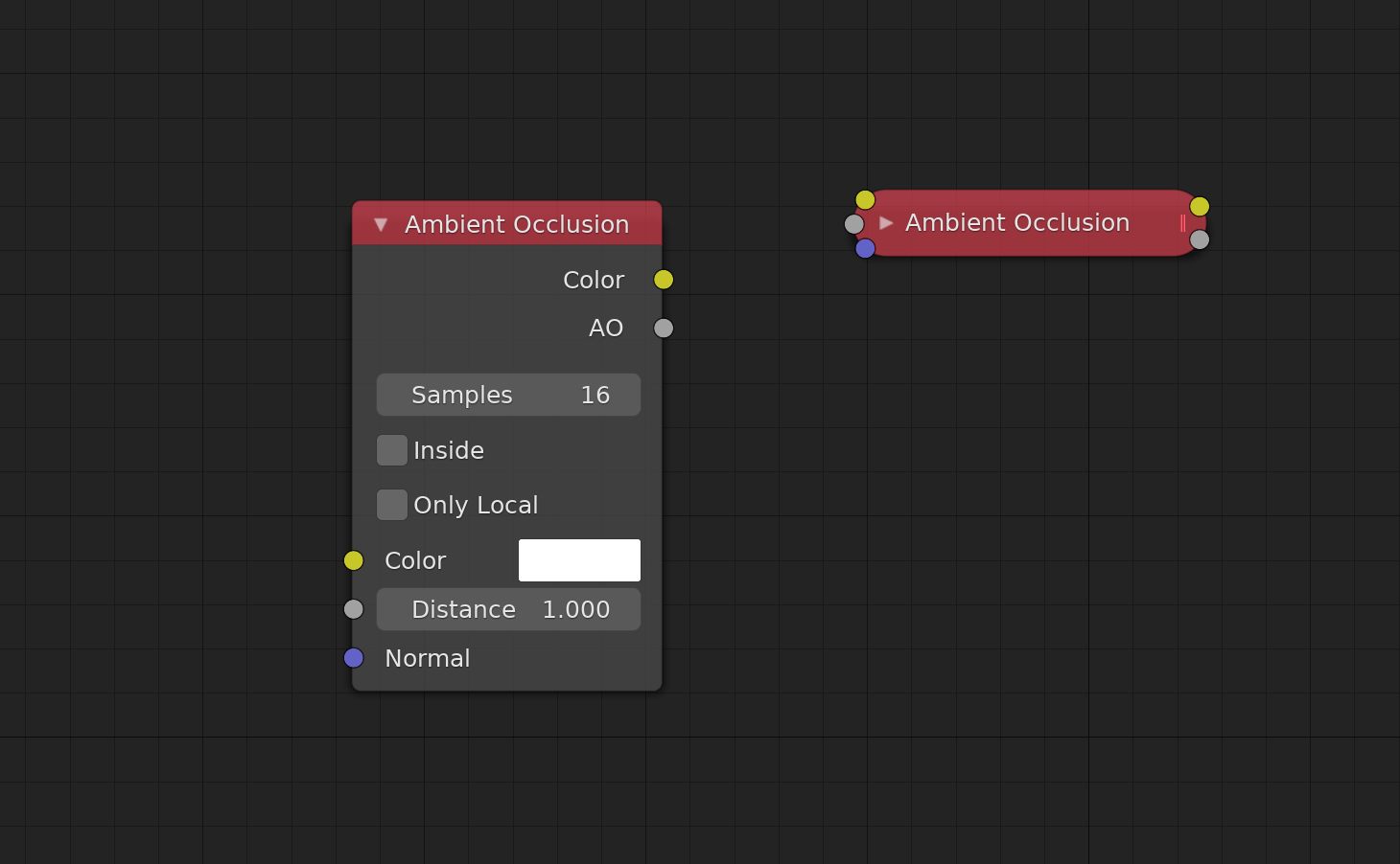
In Blender, properties are located on the node in addition to the properties panel sidebar within the node editor window. This system allows users to both set parameters which aren’t connected to another node, or view the set values when connected to other nodes, directly in the graph alongside their connections with the appropriate controls. While Blender’s nodes default to their expanded state, they can be collapsed by users as shown above by clicking the arrow next to the node name. Being a “multi in, multi out” system, Blender’s nodes do not pass every piece of data between each-other. Instead they use coloured sockets to display what data types a node can accept. The Ambient Occlusion shader node featured in this image accepts a “Colour” input for RGB data, a “Distance” input for a floating point integer, and a “Normal” input that accepts vector coordinate data. For a full list of input types, refer to Blender’s documentation page on node sockets.
Properties and Node Sizes
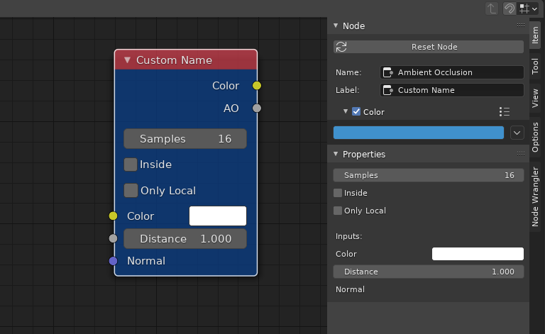
In addition to coloured sockets, Blender’s nodes follow a strict set of colour guidelines based on the type of operation that a given node performs. Unlike Nuke, the colour of the title is not user-addressable within the program. However, users are able to set a custom fill colour from within the node properties panel. The properties panel also allows users to set a custom arbitrary label that will replace its stock title, as shown here with the Ambient Occlusion node.
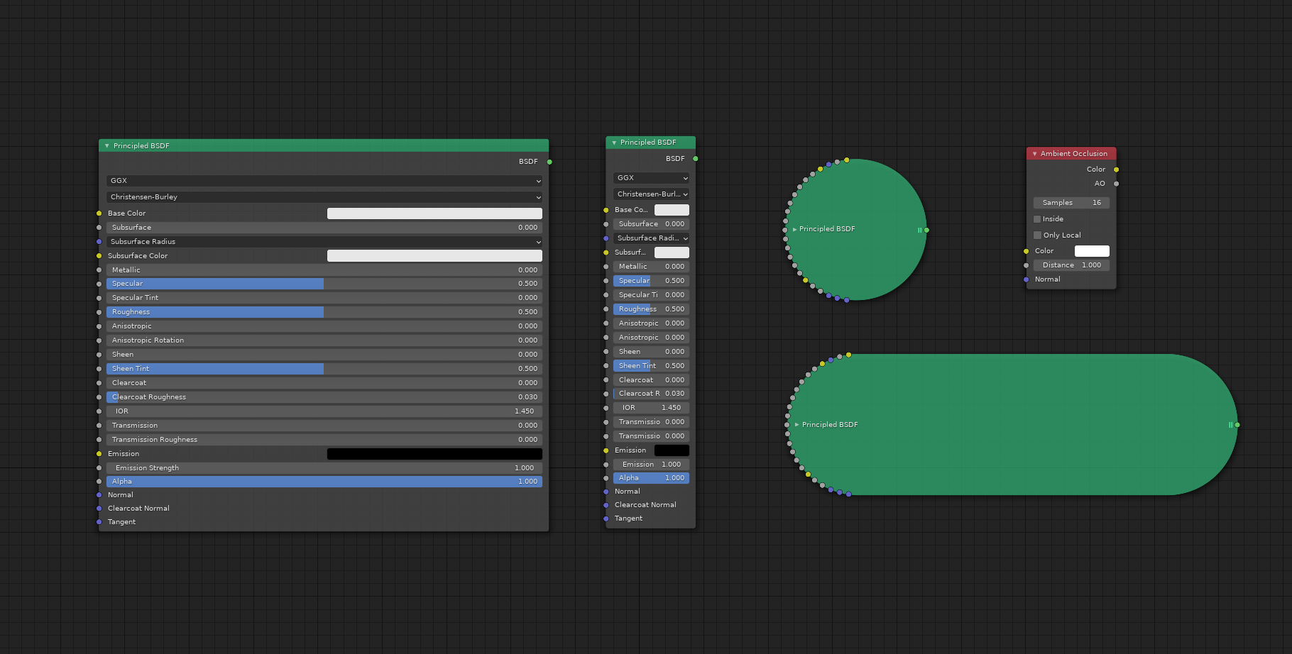
Blender’s nodes are user resizable in the graphs X axis but are a fixed size in the Y axis based on the node’s properties when expanded, or number of sockets when collapsed. This image shows Blender’s Principled BSDF shader node in its maximum and minimum scales when expanded and collapsed. The Ambient Occlusion node is also present at its default scale. Nodes with un-connected sockets can have their empty sockets hidden by the user to clean up the graph. This is especially useful when dealing with large nodes that have lots of inputs like the Principled BSDF node.
Blender’s Node-graph
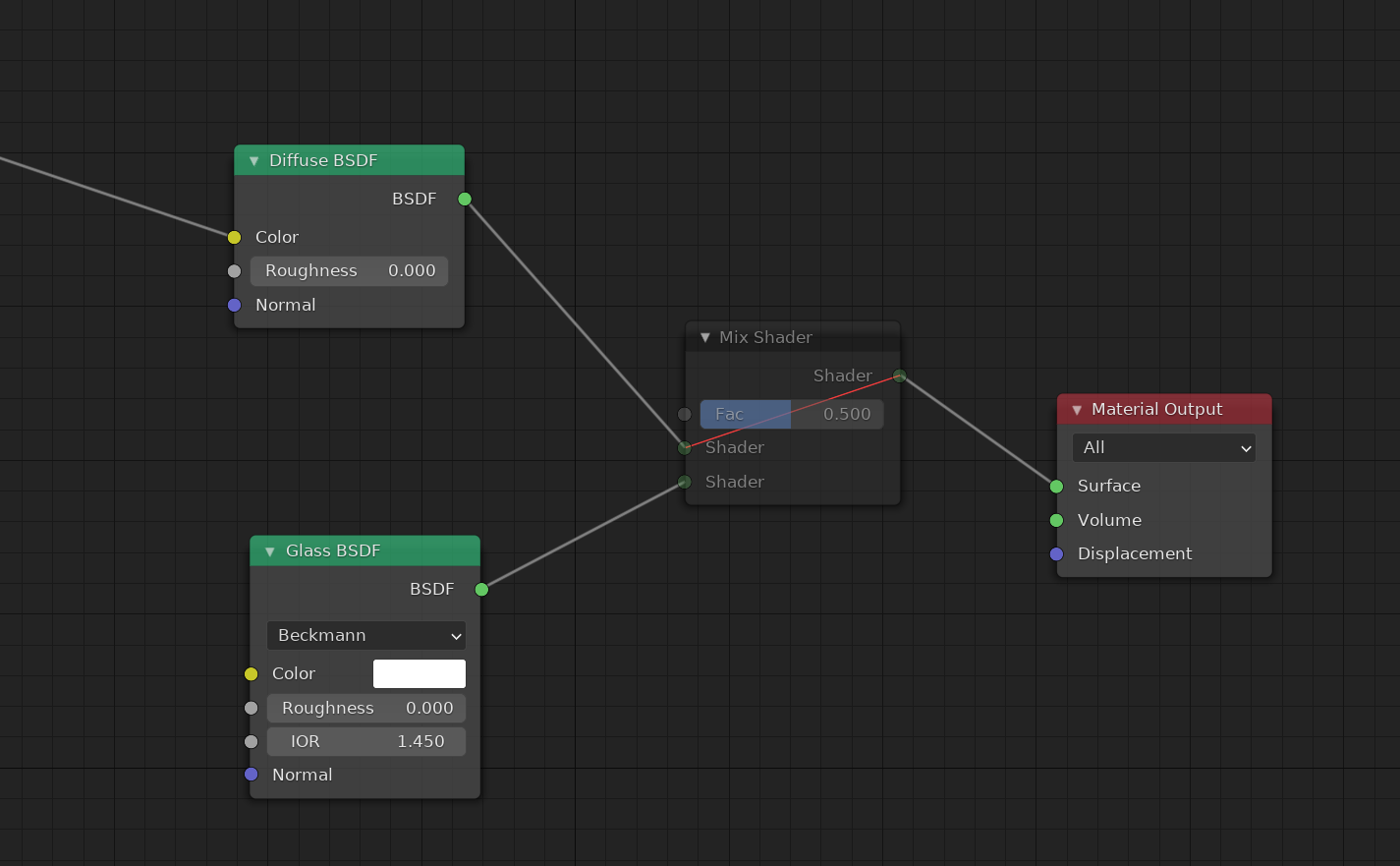
As suggested by the shape of its nodes, graphs created in Blender typically flow from left to right. Like Nuke, nodes can be muted in Blender to disable their function without removing them from the graph. Muted nodes helpfully display any relevant connections that are passed through them with a red line.
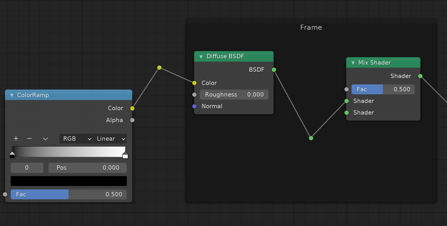
Blender allows its users to create frames to visually organize a set of nodes. Unlike Nuke, when selected the frame does not allow users to move all the nodes located within it. Blender also includes a “reroute” node which can be placed in-between any pipe by holding shift, and dragging with right click to “cut” a pipe. This implementation of node-elbows is helpfully coloured with the same data type colour as its inputs. Left clicking and dragging on reroute nodes will extend new pipes out from them and unlike other nodes it can only be moved with the middle mouse button.
Other Points of Interest
As of Blender 2.92 node-graphs cannot be copied to plain-text. The intended workflow is to save materials in a .blend file and append or link (import or reference) the relevant materials from that .blend to the current one so they can be used there.
In practice, when people share their node-graphs online it is common to post a screenshot of the node-graph where users will re-create the graph manually in order to achieve the desired effect. This is a terrible workflow and results in lots of human effort where none should be required.